Contactors Explained: Complete Guide for Beginners
Discover the working principles, components, wiring, and practical uses of contactors in a detailed guide. Perfect for electricians, automation enthusiasts, and hobbyists, this article breaks down how these devices work, where they’re used, and how to select and connect them for safe, efficient operation.
CIRCUIT CONTROL DEVICE
ELEKTRECA
8/9/20253 min read

Understanding Contactors in Detail
Introduction
A contactor is an electrically controlled switch used for switching high-power electrical circuits, mainly in motors, heaters, lighting, and other heavy loads.
While relays and contactors work on the same basic electromagnetic principle, contactors are built for higher current capacity and heavy-duty operation in industrial environments.
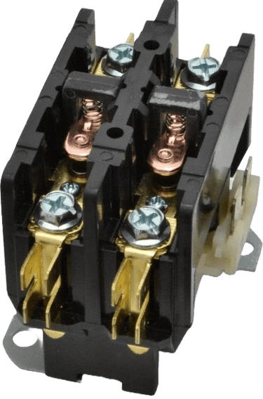
Main Components of a Contactor
Just like a relay, a contactor has a coil, armature, and contacts, but it is designed more robustly.
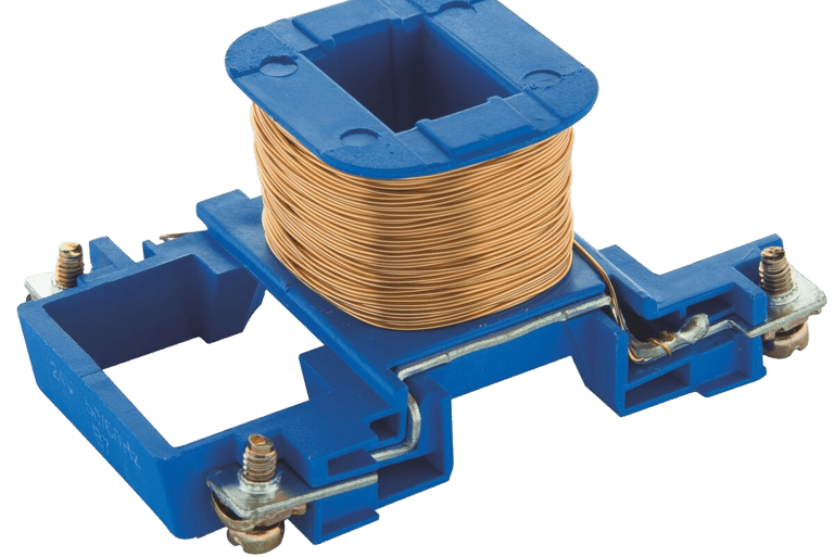
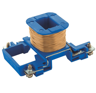
2.1. Coil (Electromagnet)
Energised by a control voltage (AC or DC), pulls the armature to close the main contacts.
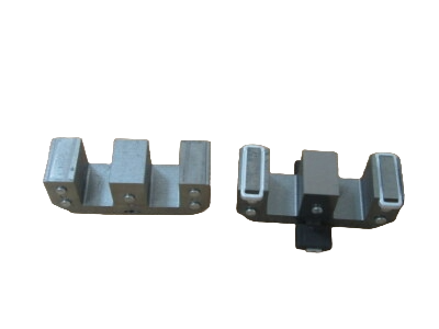
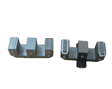
Armature
Moving the iron piece that is pulled by the coil.Moves the contacts into position.
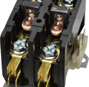
Main Contacts
Carry the load current. Usually three poles for three-phase systems (L1, L2, L3). Made of durable alloys to handle arcing and wear.
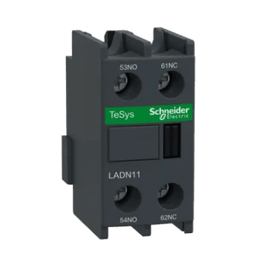
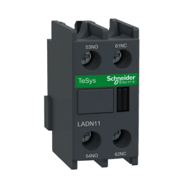
Auxiliary Contacts
Smaller contacts are used for control and signalling circuits. Available in Normally Open (NO) or Normally Closed (NC) types.
De-energised State Coil is off. Main contacts remain open, and current flows to the load.
Energised State Control voltage is applied to the coil. The magnetic field pulls the armature. Main contacts close, allowing current to flow to the load. Auxiliary contacts change state for control logic.
Returning to RestCoil voltage is removed. The spring mechanism pushes the armature back. Main contacts open, stopping power to the load.
Common Ratings for Contactors
Coil Voltage: 12V, 24V, 48V, 110V, 220V, or 415V (AC or DC).
Current Rating: From 9A up to over 1000A.
Power Rating: Specified in kW for motors (e.g., 18.5 kW @ 400V).
Applications of Contactors
Motor Starters – Used with overload relays to start and stop motors.
Lighting Circuits – Large building lighting control.
Heating Systems – Switching high-current heaters.
Capacitor Banks – Switching power factor correction capacitors.
Welding Machines – Controlling heavy currents.
Safety and Maintenance Tips
Use the correct coil voltage – Prevent overheating or failure.
Match contactor rating to load – Avoid contact welding.
Tighten terminal screws – Loose connections cause overheating.
Inspect contacts – Worn contacts should be replaced.
Check auxiliary contacts – Ensure correct operation in control circuits.
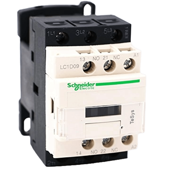
Wiring a Contactor
A basic contactor has:
A1 & A2 – Coil terminals.
L1, L2, L3 – Main input terminals.
T1, T2, T3 – Main output terminals.
Auxiliary contacts – For control logic.
When the coil (A1–A2) is energized, L1 connects to T1, L2 to T2, and L3 to T3.
Contactors in Motor Control
In motor control systems, contactors are often paired with:
Overload Relays – Protect the motor from overcurrent.
Push Buttons – Start and stop controls.
Interlocks – Prevent accidental reverse operation.
For example, in a DOL (Direct-On-Line) starter, the contactor energises when the start button is pressed, closing the main contacts and powering the motor.
Conclusion
A contactor is essentially a heavy-duty relay designed for high-power applications. Understanding its construction, working principle, and correct usage is vital in electrical installation and automation. Paired with the right control circuit, contactors make power control safe, efficient, and reliable.
Insights
Connect
info@elektreca.com
+254786927909
© 2025. All rights reserved.